Reverse Engineering Services
Bridge the gap between physical reality and digital precision. We convert existing components into high-fidelity parametric CAD models ready for manufacturing.
Why Choose Our Reverse Engineering Services?
Legacy Part Recreation
Recreate parts where original CAD data is lost or never existed
Competitive Benchmarking
Analyze competitor products for design insights and improvements
Design Optimization
Improve existing designs based on performance analysis
Failure Analysis
Investigate component failures through digital forensics
Case Study: Complex Casting Recovery
See how we recovered a $50k mold design from a damaged casting with 100% surface accuracy.
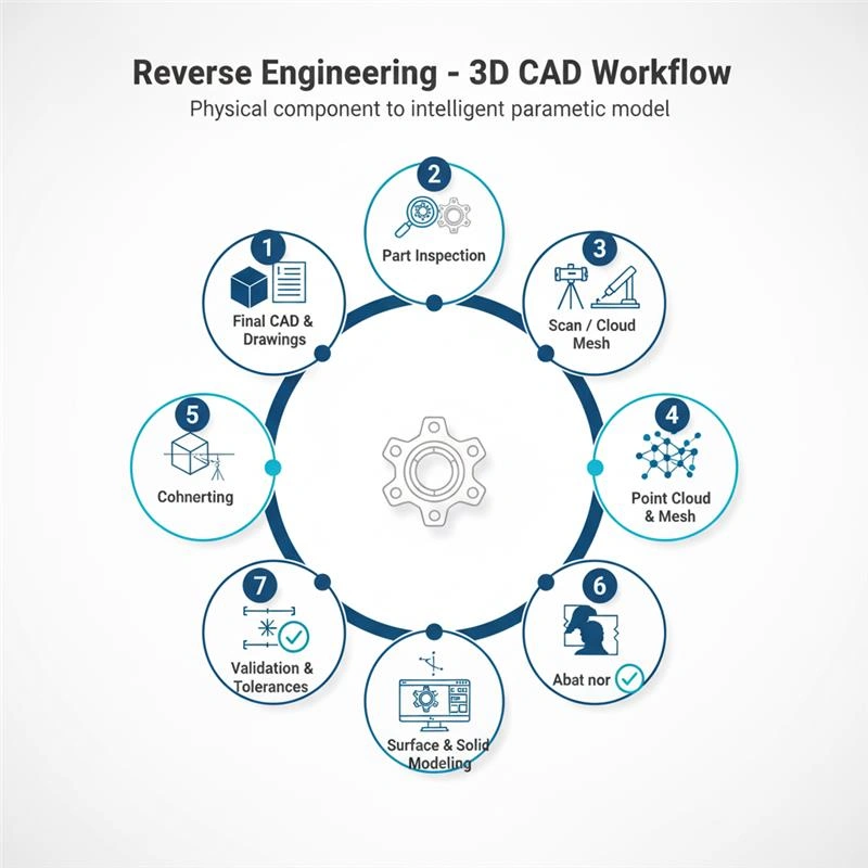
From Physical Part to Digital Master
Our systematic approach ensures every component is transformed into a fully parametric, manufacturing-ready CAD model with complete documentation and validation.
Full Paramatric Control
Models are fully editable with proper feature trees
Manufacturing Ready
Complete GD&T and tolerance specifications
Quality Guaranteed
Deviation analysis and validation reports included
Reverse Engineering Process Flow
Our structured approach ensures accurate digital reconstruction of physical components with full parametric control and manufacturing readiness.
Part inspection and intent capture
The process starts by cleaning and inspecting the physical component, understanding how it functions in the assembly, and identifying critical features, interfaces, and tolerances that must be preserved or improved. Engineers document dimensions, materials, wear areas, and design intent so the later CAD model is not just a copy of the shape, but a controlled, parametric representation of how the part is supposed to work.
Key Activities
3D scanning and measurement
Next, the part is digitized using 3D scanners, CMMs, or other metrology tools to capture its geometry with sufficient accuracy for the target tolerance. Multiple scan passes may be taken from different orientations, using markers or fixtures, to ensure complete coverage of all visible surfaces and features.
Key Activities
Point cloud and mesh processing
All raw scans are registered into a common coordinate system, merged, and cleaned to remove noise, outliers, and overlaps, creating a unified point cloud. This point cloud is then converted into a polygonal mesh, where holes are filled, edges are smoothed, and the mesh is decimated or refined as needed to balance accuracy and file size.
Key Activities
CAD reconstruction (surfaces and solids)
Using the processed mesh as a reference, engineers reconstruct the geometry in parametric CAD by fitting primitives (planes, cylinders, cones) and building sketches, surfaces, and solids that follow design intent rather than blindly copying every triangle. Freeform regions are surfaced, prismatic regions are modeled with standard features, and a clean feature tree is created so the part can be edited, toleranced, and reused like a native design.
Key Activities
Analysis, validation, and tolerance definition
The resulting CAD is aligned back to the scan or key measurement datums, and deviation analysis is performed to check how closely the model matches the real part across all critical areas. Any gaps beyond allowable limits trigger local remodeling, and at this stage GD&T and functional tolerances are defined so the part can be manufactured and inspected consistently in production.
Key Activities
Final deliverables and release
Once validated, final deliverables are generated: native CAD files, neutral formats (STEP/IGES), 2D drawings with dimensions and GD&T, and supporting inspection or deviation reports. These outputs feed directly into tooling, CNC, or additive workflows and also serve as a master reference for future design modifications, lifecycle management, or digital twin applications.
Key Activities
Advanced Tools & Comprehensive Deliverables
Advanced Technologies
We utilize state-of-the-art scanning technologies to capture even the most complex geometries with precision.
Final Deliverables
We provide comprehensive outputs ready for manufacturing, analysis, and future modifications.
Native CAD
Neutral Formats
2D Drawings
Analysis Reports
Precision You Can Trust
Our reverse engineering process delivers exceptional accuracy and quality
Scanning Accuracy
Hours Turnaround
Parametric Models
Projects Completed
Frequently Asked Questions
Got questions about our services? Find the answers here.
Ready to Transform Physical Parts into Digital Precision?
Send us your physical component, and we'll deliver production-ready CAD models with full documentation and validation.
