2K Injection Molding: Advanced Engineering Guide
Introduction: The Revolution in Multi-Material Manufacturing
In today's competitive automotive industry, 2K injection molding (also known as two-shot or dual-shot molding) has emerged as a game-changing technology that enables the creation of complex components with multiple materials in a single manufacturing cycle. This advanced process combines the structural benefits of rigid polymers with the functional advantages of elastomers, opening new possibilities for automotive interior design, functionality, and manufacturing efficiency.
The global 2K injection molding market is projected to reach $15.8 billion by 2027, driven primarily by automotive demand for lightweight, integrated components that reduce assembly time and improve vehicle aesthetics. For automotive engineers and manufacturers, mastering 2K molding is no longer optional—it's essential for competitive advantage.
This comprehensive guide will equip you with the technical knowledge to design, implement, and optimize 2K injection molding processes for automotive applications.
What is 2K Injection Molding?
Definition and Core Concept
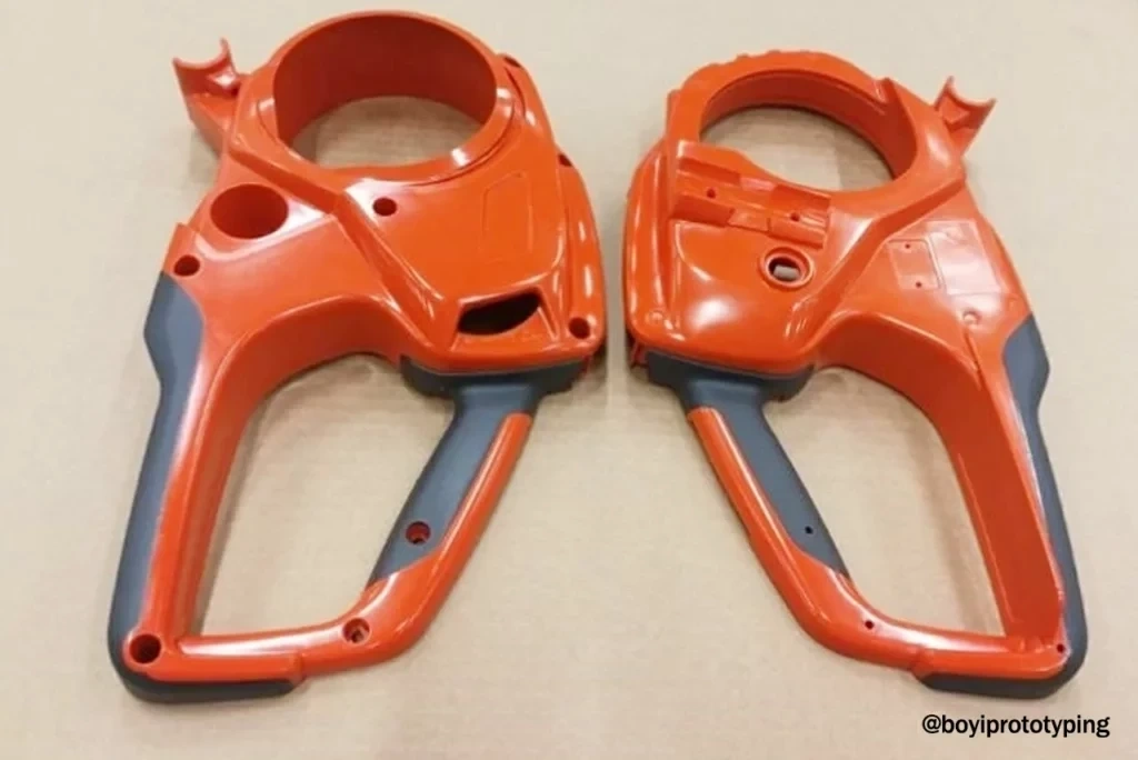
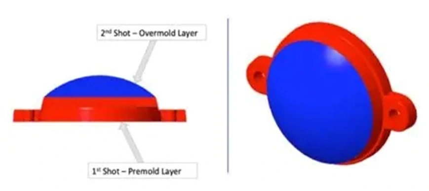
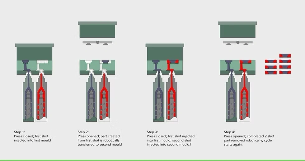
*2K injection molding** is an advanced manufacturing process that injects two different materials or colors into a single mold during one continuous cycle, creating a permanently bonded multi-material component. Unlike traditional overmolding processes that require multiple operations, 2K molding achieves material integration in a single cycle, ensuring perfect alignment and superior bond strength.
Evolution from Single-Material Molding
*Traditional Single-Material Limitations:**
Limited functionality (single material properties)
Requires secondary operations for features like soft-touch areas
Multiple assembly steps increase cost and complexity
Design constraints due to material property limitations
*2K Molding Advantages:**
Integrated multi-functionality in single component
Reduced assembly operations and labor costs
n- Enhanced design freedom and aesthetics
Superior material bonding through molecular fusion
Key Differentiators from Other Processes
*vs. Traditional Overmolding:**
2K: Single cycle, simultaneous material integration
Overmolding: Multiple cycles, sequential material addition
*vs. Insert Molding:**
2K: Both materials injected as molten polymers
Insert molding: Pre-formed inserts placed in mold
*vs. Co-Injection:**
2K: Distinct material layers with clear boundaries
Co-injection: Materials blend at interface
The 2K Injection Molding Process: Technical Deep Dive
Step 1: Advanced Mold Design and Tool Creation
*Dual-Cavity Mold Architecture:**
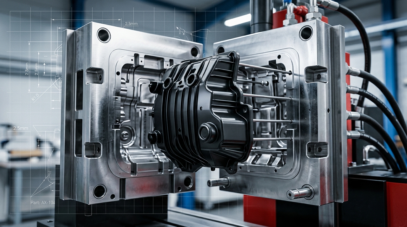
The foundation of 2K molding lies in sophisticated mold design that incorporates two distinct cavities with precise alignment and material transfer mechanisms.
*Critical Design Elements:**
Rotational Indexing Systems: Enable precise cavity positioning
Material Separation Barriers: Prevent cross-contamination between materials
Thermal Management Zones: Independent temperature control for each material
Ejection Systems: Coordinated release of multi-material parts
*Tooling Complexity Factors:**
Precision Requirements: ±0.01mm alignment tolerance between cavities
Material Compatibility: Tool steel selection for different polymer families
Cycle Time Optimization: Balanced heating/cooling for both materials
Maintenance Considerations: Access for cleaning and wear replacement
*Investment Considerations:**
Tool Cost: 2-3x traditional single-material molds
Development Time: 16-24 weeks vs. 8-12 weeks standard
ROI Period: 18-36 months depending on production volume
Step 2: First Shot (Substrate Material Injection)
*Material Selection Criteria:**
The substrate material typically provides the structural foundation and must meet specific requirements:
*Mechanical Properties:**
High tensile strength (50-80 MPa typical)
Good impact resistance (Izod 100-300 J/m)
Dimensional stability (CTE 50-100 μm/m°C)
Surface hardness appropriate for application
*Processing Characteristics:**
Melt flow index compatible with equipment
Appropriate viscosity for first cavity filling
Suitable thermal properties for second shot bonding
Minimal shrinkage variation
*Common Automotive Substrate Materials:**
ABS: Good balance of strength and processability
Polycarbonate (PC): High impact resistance and temperature tolerance
Polypropylene (PP): Chemical resistance and low density
Nylon (PA6/PA66): High strength and wear resistance
*Process Parameters:**
Injection Pressure: 800-1,500 bar
Melt Temperature: 220-280°C (material dependent)
Mold Temperature: 60-100°C
Cooling Time: 15-30 seconds (part geometry dependent)
Step 3: Mold Repositioning and Transfer Mechanisms
*Rotary Platen Systems:**
*Working Principle:**
The entire mold half rotates 180° to position the partially formed substrate under the second injection unit. This system provides the highest precision and is ideal for high-volume automotive applications.
*Technical Specifications:**
Rotation Accuracy: ±0.005mm
Cycle Time Impact: 2-4 seconds additional
Suitable Part Size: Up to 500mm x 500mm
Maintenance Interval: 50,000-100,000 cycles
*Index Plate Systems:**
*Working Principle:**
Multiple core plates index within the same mold base, allowing sequential material injection without full mold rotation. This system offers faster cycle times for smaller components.
*Technical Specifications:**
Index Accuracy: ±0.01mm
Cycle Time Impact: 1-2 seconds additional
Suitable Part Size: Up to 200mm x 200mm
Cavity Configurations: 2-8 cavities typical
*Core-Back/Retractable Core Systems:**
*Working Principle:**
Selected core sections retract to create space for second material injection, enabling complex 3D material integration without rotational movement.
*Applications:**
Sealing interfaces with integrated soft-touch
Structural components with embedded flexible elements
Complex geometries requiring material undercuts
Step 4: Second Shot (Overmold Material Injection)
*Material Selection Criteria:**
Overmold materials must provide complementary functionality while maintaining compatibility with the substrate.
*Elastomeric Materials:**
Thermoplastic Elastomers (TPE): Flexible, rubber-like properties
Thermoplastic Polyurethanes (TPU): Excellent abrasion resistance
Silicone-Based Compounds: High temperature resistance
*Functional Additives:**
Anti-Microbial Agents: For high-touch surfaces
UV Stabilizers: For exterior applications
Flame Retardants: For safety-critical components
Conductive Fillers: For EMI shielding applications
*Process Optimization:**
Temperature Matching: Substrate surface temperature critical for bonding
Pressure Control: Lower pressure prevents substrate deformation
Gate Design: Optimized for multi-material flow
Ventilation: Critical for complex geometries
Step 5: Integrated Cooling and Ejection
*Dual-Zone Temperature Control:**
Substrate Zone: Maintained at optimal bonding temperature
Overmold Zone: Optimized for material solidification
Transition Zone: Prevents thermal shock at material interface
*Ejection System Design:**
Sequential Ejection: Prevents part distortion
Stripper Plates: For delicate surface areas
Air-Assisted Ejection: For complex geometries
Robotic Handling: For high-volume production
Material Compatibility: The Science of Molecular Bonding
Chemical Bonding Mechanisms
*Polymer Chain Interdiffusion:**
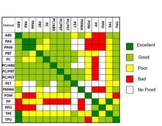
When compatible polymers are combined at molecular level, polymer chains from both materials interdiffuse across the interface, creating a seamless bond that can approach the strength of the base materials.
*Critical Factors for Chemical Bonding:**
Solubility Parameter Matching: ±2.0 MPa^0.5 for optimal bonding
Surface Energy Compatibility: Similar polarity characteristics
Molecular Weight Distribution: Appropriate chain mobility
Processing Temperature: Sufficient thermal energy for interdiffusion
*Compatible Material Families:**
| Substrate | Compatible Overmolds | Bond Strength (MPa) |
|------------|---------------------|-------------------|
| ABS | TPE, TPU, PC | 8-15 |
| Polycarbonate | TPU, PC, ABS | 10-18 |
| Polypropylene | TPO, PP-based TPE | 6-12 |
| Nylon | TPU, PA-based TPE | 12-20 |
Mechanical Bonding Strategies
*Surface Preparation Techniques:**
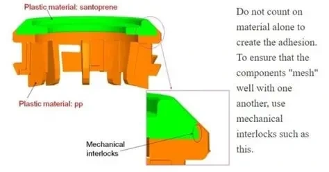
When chemical compatibility is limited, mechanical bonding strategies create physical interlocking between materials.
*Design Features for Mechanical Bonding:**
Undercut Geometry: Creates physical barriers to separation
Porous Surface Structure: Increases surface area for mechanical grip
Textured Interfaces: Micro-scale mechanical interlocking
Interlocking Features: Dovetail or tongue-and-groove designs
*Laser Texturing Applications:**
Pattern Types: Grid, radial, or random textures
Feature Size: 10-100 μm typical
Depth Control: 20-200 μm for optimal bonding
Coverage Area: 100% of interface recommended
Thermal Expansion Management
*Coefficient of Thermal Expansion (CTE) Matching:**
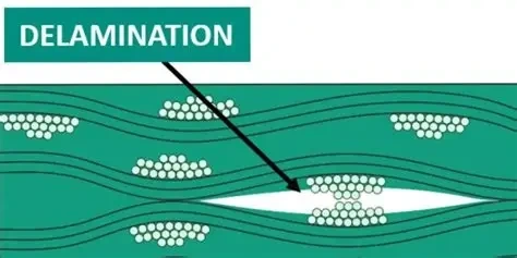
Differential thermal expansion between materials can create internal stresses during temperature cycling, potentially leading to delamination or failure.
*CTE Values for Common Materials:**
ABS: 70-90 μm/m°C
Polycarbonate: 65-70 μm/m°C
TPE: 100-200 μm/m°C
TPU: 80-150 μm/m°C
Nylon: 80-100 μm/m°C
*Design Strategies for CTE Mismatch:**
Compliance Layers: Intermediate materials to reduce stress
Geometric Compensation: Design features to absorb differential movement
Operating Temperature Range: Design for specific service conditions
Finite Element Analysis: Predict stress concentrations
Automotive Applications: Real-World Implementation
Interior Components
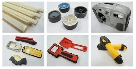
*Dashboard and Console Applications:**
*Soft-Touch Integration:**
Application: Instrument panel surfaces, door handles
Materials: ABS substrate + TPE overmold
Benefits: Enhanced tactile feel, reduced vibration noise
Design Considerations: Wear resistance, UV stability
*Structural and Functional Integration:**
Application: Center console structures with integrated soft-touch elements
Materials: Polycarbonate substrate + TPU overmold
Benefits: Reduced part count, assembly simplification
Technical Requirements: Impact resistance, temperature stability
*Switch and Control Interfaces:**
Application: HVAC controls, infotainment buttons
Materials: PC substrate + silicone-based overmold
Benefits: Waterproof sealing, enhanced ergonomics
Critical Factors: Actuation force consistency, long-term durability
Exterior Components
*Lighting and Sensor Integration:**
Application: Headlamp housings, sensor enclosures
Materials: PC substrate + UV-stabilized TPU
Benefits: Integrated sealing, vibration damping
Technical Challenges: Weather resistance, optical clarity
*Exterior Trim and Accents:**
Application: Window seals, exterior handles
Materials: PP substrate + EPDM-based overmold
Benefits: Weather resistance, color integration
Critical Requirements: UV stability, temperature extremes
Under-the-Hood Applications
*Sealing and Gasket Components:**
Application: Valve covers, sensor housings
Materials: Nylon substrate + high-temperature TPU
Benefits: Integrated sealing, chemical resistance
Technical Challenges: Temperature resistance, oil compatibility
*Vibration Damping Components:**
Application: Engine mounts, transmission components
Materials: Glass-filled nylon + vibration-damping elastomer
Benefits: Noise reduction, integrated functionality
Critical Factors: Fatigue resistance, temperature stability
Process Optimization and Quality Control
Cycle Time Optimization
*Sequential Processing Strategies:**
Parallel Operations: Overlap cooling and preparation steps
Optimized Temperature Profiles: Reduce heating/cooling time
Rapid Ejection Systems: Minimize part removal time
Automated Material Handling: Reduce manual intervention
*Typical Cycle Times by Application:**
| Application | Part Size | Cycle Time | Production Rate |
|-------------|------------|-------------|-----------------|
| Interior Switch | 50mm x 30mm | 15-20 seconds | 180-240 parts/hour |
| Door Handle | 200mm x 80mm | 30-45 seconds | 80-120 parts/hour |
| Dashboard Panel | 400mm x 300mm | 60-90 seconds | 40-60 parts/hour |
| Console Structure | 600mm x 400mm | 90-120 seconds | 30-40 parts/hour |
Quality Assurance Systems
*In-Process Monitoring:**
Cavity Pressure Sensors: Real-time fill monitoring
Temperature Control: Multi-zone thermal management
Vision Systems: Automated defect detection
Statistical Process Control: Real-time capability monitoring
*Post-Process Inspection:**
Dimensional Verification: CMM measurement of critical features
Bond Strength Testing: Peel and shear tests for interface integrity
Visual Inspection: Surface quality and cosmetic defects
Functional Testing: Assembly fitment and operation verification
*Common Defects and Solutions:**
| Defect Type | Root Cause | Corrective Action |
|--------------|-------------|------------------|
| Delamination | Material incompatibility | Review material selection, increase surface temperature |
| Flash | Excessive injection pressure | Optimize pressure profile, improve mold sealing |
| Short Shots | Insufficient material volume | Adjust shot size, check material viscosity |
| Sink Marks | Inadequate packing pressure | Optimize packing profile, adjust gate design |
| Weld Lines | Improper flow front meeting | Optimize gate location, increase melt temperature |
Cost Analysis and Economic Considerations
Tooling Investment Analysis
*Initial Investment Breakdown:**
Mold Base and Hardware: 40-50% of total cost
Cavity Machining: 25-35% of total cost
Rotary/Index Mechanism: 15-20% of total cost
Temperature Control System: 5-10% of total cost
*Cost Comparison by Production Volume:**
| Production Volume | 2K Tool Cost | Traditional Assembly Cost | Breakeven Point |
|------------------|----------------|------------------------|------------------|
| 50,000 units | $150,000 | $2.50/unit | 60,000 units |
| 100,000 units | $180,000 | $2.25/unit | 80,000 units |
| 500,000 units | $250,000 | $1.80/unit | 140,000 units |
| 1,000,000 units | $300,000 | $1.50/unit | 200,000 units |
Per-Part Cost Analysis
*Material Costs:**
Substrate Material: $2.50-8.00/kg (material dependent)
Overmold Material: $4.00-12.00/kg (elastomer premium)
Material Utilization: 85-95% (including regrind)
Total Material Cost: $0.50-3.00 per part (size dependent)
*Processing Costs:**
Machine Hour Rate: $80-150/hour (machine size dependent)
Labor Requirements: 0.5-1.0 operators per machine
Energy Consumption: 15-25 kWh per hour
Maintenance Costs: $5,000-15,000 per year
*Quality and Testing Costs:**
Inspection Time: 30-60 seconds per part
Testing Equipment: $50,000-100,000 initial investment
Statistical Process Control: $0.10-0.25 per part
Warranty Reserve: 1-3% of part cost
Advanced Technologies and Future Trends
Multi-Material Integration Beyond 2K
*3K and 4K Molding Systems:**
Technology Overview: Integration of 3-4 materials in single cycle
Current Applications: High-end automotive interior components
Technical Challenges: Material compatibility, cycle time management
Future Potential: Integrated electronics, smart materials
*Hybrid Injection Molding:**
Technology Integration: Combining injection molding with other processes
Examples: Insert molding with metal components, textile integration
Benefits: Enhanced functionality, reduced assembly steps
Challenges: Process synchronization, quality control
Industry 4.0 Integration
*Smart Manufacturing Systems:**
IoT Sensors: Real-time process monitoring and optimization
Machine Learning: Predictive quality and process adjustment
Digital Twins: Virtual process optimization and simulation
Cloud-Based Quality Management: Remote monitoring and analysis
*Data Analytics Applications:**
Predictive Maintenance: Equipment failure prevention
Quality Prediction: Real-time defect detection
Process Optimization: Automated parameter adjustment
Supply Chain Integration: Just-in-time material delivery
Sustainable Manufacturing
*Recycled Material Integration:**
Post-Consumer Content: Up to 30% recycled content in non-critical areas
Post-Industrial Content: Up to 50% recycled content in substrate
Material Performance: Maintaining properties with recycled content
Certification Requirements: Automotive industry standards
*Energy Efficiency Improvements:**
Servo-Electric Machines: 30-50% energy reduction
Heat Recovery Systems: Capture and reuse thermal energy
Optimized Cooling: Variable flow temperature control
Renewable Energy: Solar and wind power integration
Design Guidelines for Engineers
Design for Manufacturability (DFM)
*Material Selection Guidelines:**
Compatibility First: Ensure chemical or mechanical bonding viability
Processing Temperature: Match material processing windows
Shrinkage Matching: Minimize differential shrinkage
Service Requirements: Consider temperature, chemical exposure, UV exposure
*Geometry Optimization:**
Uniform Wall Thickness: 2-4mm typical for automotive applications
Draft Angles: 1-3° for substrate, 2-5° for overmold
Radius Design: Minimum 0.5mm for material flow
Gate Location: Optimize for balanced filling
*Interface Design:**
Bonding Area: Maximize interface surface area
Stress Concentration: Avoid sharp corners at material boundaries
Transition Zones: Gradual material transitions where possible
Assembly Integration: Design for final assembly requirements
Simulation and Analysis
*Mold Flow Analysis:**
Fill Pattern Prediction: Optimize gate location and size
Weld Line Prediction: Identify and relocate potential weak points
Cooling Analysis: Optimize temperature control
Warpage Prediction: Compensate in tool design
*Structural Analysis:**
Bond Strength Simulation: Predict interface performance
Thermal Analysis: Evaluate CTE mismatch effects
Impact Simulation: Verify drop and impact performance
Fatigue Analysis: Assess long-term durability
Implementation Strategy for Manufacturers
Phase 1: Technology Assessment
*Capability Evaluation:**
Current Equipment: Assess compatibility with 2K requirements
Technical Expertise: Evaluate team knowledge and training needs
Quality Systems: Review current quality control capabilities
Supply Chain: Assess material supplier capabilities
*Feasibility Analysis:**
Part Selection: Identify suitable applications for 2K implementation
Cost-Benefit Analysis: Calculate ROI for specific applications
Risk Assessment: Identify potential challenges and mitigation strategies
Timeline Development: Create realistic implementation schedule
Phase 2: Pilot Program Implementation
*Equipment Selection:**
Machine Specifications: Tonnage, platen size, injection units
Mold Design: Select appropriate mold configuration
Auxiliary Equipment: Temperature control, material handling
Safety Systems: Ensure compliance with safety standards
*Process Development:**
Material Qualification: Test and validate material combinations
Process Optimization: Establish optimal processing parameters
Quality System Development: Implement inspection and testing procedures
Operator Training: Develop comprehensive training programs
Phase 3: Full-Scale Production
*Production Ramp-Up:**
Gradual Volume Increase: Systematic capacity expansion
Process Refinement: Continuous optimization based on production data
Quality Improvement: Implement statistical process control
Cost Optimization: Identify and eliminate waste
*Continuous Improvement:**
Performance Monitoring: Track key performance indicators
Technology Updates: Evaluate new technologies and processes
Market Expansion: Identify new applications and opportunities
Capability Development: Expand technical expertise and capacity
Conclusion: Strategic Advantage Through 2K Molding
2K injection molding represents a significant technological advancement in automotive manufacturing, enabling the creation of complex, integrated components that were previously impossible or cost-prohibitive. The technology offers compelling advantages:
*Key Benefits Achieved:**
Assembly Reduction: 30-70% fewer assembly operations
Cost Savings: 15-40% total cost reduction for suitable applications
Weight Reduction: 10-25% through part integration
Quality Improvement: Enhanced consistency and reliability
Design Freedom: Expanded creative possibilities for designers
*Strategic Considerations:**
Investment Requirements: Significant initial tooling investment
Technical Complexity: Requires specialized expertise and equipment
Material Science: Critical understanding of polymer compatibility
Quality Control: Sophisticated inspection and testing requirements
For automotive manufacturers and suppliers, 2K injection molding is not just a manufacturing process—it's a strategic capability that enables competitive advantage through product innovation, cost reduction, and quality enhancement.
How MG Techworks Can Help
At MG Techworks, we provide comprehensive 2K injection molding expertise:
Material Selection and Compatibility Analysis for optimal material combinations
Mold Design and Development for complex multi-material applications
Process Optimization for maximum efficiency and quality
Quality System Implementation for automotive-grade production
Cost Reduction Analysis for ROI optimization
Our team of experienced polymer engineers and manufacturing specialists has helped leading automotive manufacturers successfully implement 2K molding technologies and achieve significant competitive advantages.
*Ready to implement 2K injection molding in your manufacturing process?**
Contact MG Techworks to discover how our expertise in multi-material molding can transform your product development and manufacturing capabilities.
Explore our Product Design services or learn more about our Engineering Solutions for advanced manufacturing applications.*