7 Plastic Part Design Mistakes to Avoid in Injection Molding: A Practical DFM Guide
A plastic part can look perfect in a 3D CAD model and still create serious problems during tooling, injection molding, assembly, or production.
Issues such as sink marks, warpage, short shots, weld lines, poor ejection, dimensional variation, cracks, and assembly problems often have their roots in decisions made much earlier—during product and part design.
This is why Design for Manufacturability (DFM) should not be treated as a final inspection step. For injection-molded plastic components, manufacturability needs to influence the design from the very beginning.
For automotive components, consumer products, industrial enclosures, and other molded plastic applications, designers need to consider not only how a component looks in CAD, but also how the material will flow, cool, shrink, eject, assemble, and perform throughout its lifecycle.
In this guide, we discuss 7 common plastic part design mistakes and explain how engineers can avoid them through better DFM practices.
--
What Is Plastic Part Design for Injection Molding?
Plastic part design for injection molding is the process of developing a component so that it meets its functional, aesthetic, dimensional, and assembly requirements while also being practical to manufacture using an injection molding process.
A successful design must balance:
*Function → Material → Geometry → DFM → Tooling → Molding → Assembly → Quality**
A CAD model represents the intended geometry. DFM evaluates whether that geometry can be manufactured consistently and economically.
Modern injection-molding DFM reviews commonly consider wall thickness, draft, ribs, bosses, radii, gates, parting lines, undercuts, ejection, shrinkage, tolerances, and material behavior.
--
7 Common Plastic Part Design Mistakes
1. Ignoring Uniform Wall Thickness
One of the most common problems in injection-molded plastic part design is excessive variation in wall thickness.
When a designer makes a section unnecessarily thick to increase strength, the thicker region may cool at a different rate from the surrounding material.
This can contribute to:
Sink marks
Differential shrinkage
Warpage
Internal stresses
Dimensional variation
Longer cooling cycles
Increased material consumption
*Better approach:**
Instead of simply adding material, consider using:
Ribs
Gussets
Strategic reinforcement
Local geometry changes
Proper material selection
The objective is not to make every feature identical. The objective is to maintain a practical and controlled nominal wall while avoiding abrupt thickness transitions.
*Engineering principle:**
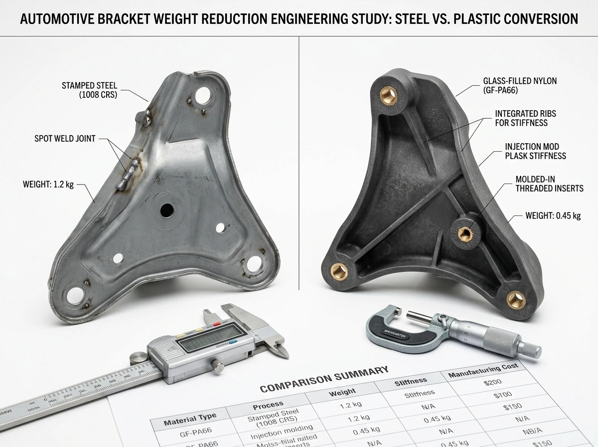
More plastic does not automatically mean more strength.* A well-designed rib can provide stiffness without creating the same thick-section problems as a solid block. Current injection-molding design guidance consistently identifies uniform wall thickness as one of the most important DFM considerations.
```text
Diagram 1 — Wall Thickness
BAD DESIGN BETTER DESIGN
┌──────────────┐ ┌──────────────┐
│ │ │ │
│ ██████ │ │ │ │
│ ██████ │ │ │ │
│ ██████ │ │ │ │
└──────────────┘ └──────────────┘
Thick section Uniform wall
→ Sink / shrinkage → Better cooling
→ Higher material → Better manufacturability
```
2. Designing Vertical Walls Without Sufficient Draft Angle
A molded part needs to be released from the mold after cooling. If a wall has little or no draft, it can drag against the mold surface during ejection.
This can result in:
Scuffing and drag marks
Ejection damage and part distortion
Increased ejector force and tool wear
Difficult mold release
*What is a draft angle?**
A draft angle is a small taper intentionally added to a molded feature so that the component can release from the mold more easily.
A common starting point for many smooth injection-molded surfaces is approximately 1°–2° per side, but the appropriate value depends on material, wall depth, texture, surface finish, molding direction, and tooling conditions. Textured surfaces often require additional draft.
Draft should also be considered for ribs, bosses, deep pockets, internal walls, slots, cosmetic surfaces, and textured features.
*Engineering principle:**
Define the mold opening direction before finalizing draft. Draft should be designed around the actual tooling strategy rather than added at the end of the CAD process.
```text
Diagram 2 — Draft Angle
WITHOUT DRAFT WITH DRAFT
│ │ ╲ ╱
│ │ │ │
│ │ │ │
│ │ ╲ ╱
╲ ╱
╲╱
Difficult release Easier release
```
3. Making Ribs Too Thick
Ribs are widely used in plastic product design to increase stiffness without significantly increasing the overall wall thickness. However, an oversized rib can create a new problem.
If the rib becomes too thick, it creates a localized material concentration that can produce a sink mark on the opposite cosmetic surface.
*Common rib design problems:**
Rib thickness equal to the main wall
Excessive rib height or no draft
Sharp rib-to-wall transition
Insufficient spacing
Poor connection to surrounding structure
A practical starting point used in many DFM guides is approximately 40%–60% of the adjacent nominal wall thickness for rib thickness, with the final value depending on material, geometry, molding process, and appearance requirements.
*Better approach:**
Use ribs to create stiffness while controlling: Thickness + Height + Draft + Radius + Spacing
*Engineering principle:**
Design ribs for stiffness—not as solid blocks of plastic.
4. Poor Boss Design
Bosses are commonly used for screws, inserts, locating features, fasteners, assembly alignment, and mounting points.
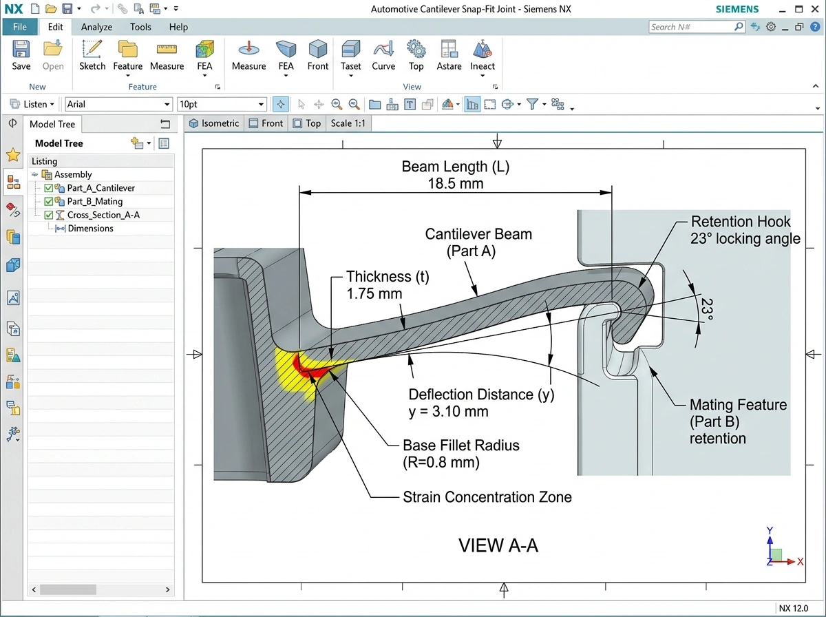
However, bosses can create thick sections if they are designed as solid cylinders directly on a plastic wall. That can lead to sink marks, warpage, stress concentration, cracking, poor screw retention, and difficult molding.
*Better boss design:**
A boss should generally be:
Properly cored
Supported with ribs where necessary
Designed with suitable draft
Integrated with the surrounding structure
Checked against the fastening requirement
The exact boss geometry should be determined from the screw, insert, load requirement, material, and manufacturing process rather than applying one universal dimension.
*Engineering principle:**
A boss should be designed as part of the assembly system—not as an isolated cylinder.
5. Ignoring Shrinkage and Warpage
Plastic does not behave like a rigid CAD model during injection molding. The material is heated, injected, packed, cooled, and ejected. During cooling, the polymer undergoes shrinkage.
If different areas of a component cool or shrink differently, the part can distort. This is commonly observed as warpage.
*What can contribute to warpage?**
Non-uniform wall thickness
Uneven cooling and gate location
Material selection and fiber orientation
Packing conditions and mold temperature
Geometry, residual stress, and part orientation
For this reason, shrinkage should be considered during product development rather than only after the first molded samples are produced.
*Engineering principle:**
Do not wait for the first molded part to discover a design problem. DFM and mold-flow or simulation studies can help identify risks before tooling is finalized.
6. Poor Corner and Fillet Design
Sharp internal corners can create stress concentrations and can also make material flow and tooling more challenging.
A plastic component designed with unnecessary sharp corners may experience higher local stress, crack initiation, difficult material flow, tooling complications, and reduced durability.
*Better approach:**
Use appropriate radii and fillets while maintaining functional requirements. A radius can help reduce stress concentration, improve material flow, improve tool manufacturability, and improve durability.
However, oversized radii should also be reviewed because they can unintentionally create thicker sections.
*Engineering principle:**
Use the right radius—not simply the largest radius possible. The radius must work together with: Wall thickness + tooling + material + function + cosmetic requirements.
7. Ignoring DFM Until After the CAD Model Is Finished
This is one of the most expensive mistakes.
A common development sequence looks like this:
CAD Complete → Tooling → Trial → Problem Found → CAD Change → Tool Modification → Retest*
The problem is not necessarily the tooling. Often, the root cause was a design decision that should have been reviewed before the mold was released.
*A better process uses simultaneous engineering:**
Concept Design → Material Selection → Mold Opening Direction → DFM Review → Draft/Wall/Rib/Boss Review → Parting Line & Gate Strategy → Tolerance & GD&T Review → Tooling Feasibility → Prototype/Simulation → Tool Release → Mold Trial → Production Validation
This approach can reduce late-stage engineering changes and improve first-time-right manufacturing outcomes.
MG Techworks provides engineering services covering Automotive Interior Plastic Design, Simultaneous Engineering – DFM & DFA, tooling feasibility, Detailed Engineering & CAD Services, and dimensional management, making early-stage manufacturability review an important part of the product-development workflow.
--
Plastic Part DFM Checklist Before Tooling
Before releasing a plastic component for tooling, engineers should review the following:
| DFM Check | Key Question |
|-----------|--------------|
| Wall Thickness | Is the wall thickness consistent and suitable for the material? |
| Draft Angle | Can every molded feature release from the tool? |
| Ribs | Are ribs providing stiffness without excessive material concentration? |
| Bosses | Are mounting features properly supported and cored? |
| Radii | Are sharp corners avoided where function permits? |
| Parting Line | Is the parting line practical for the geometry and appearance? |
| Gate Location | Can the proposed gate provide suitable filling and packing? |
| Undercuts | Can unnecessary slides or lifters be avoided? |
| Ejection | Is there sufficient ejector access and draft? |
| Shrinkage | Has material-specific shrinkage been considered? |
| Warpage | Could geometry or process create distortion? |
| Tolerances | Are critical dimensions realistically toleranced? |
| GD&T | Are functional requirements clearly defined? |
| Assembly | Does the part achieve the required fit and function? |
| Tooling | Can the proposed geometry be manufactured efficiently? |
--
Plastic Part Design: CAD vs DFM
One of the biggest misunderstandings in product development is assuming that a finished CAD model is automatically production-ready.
CAD answers: What should the part look like?
DFM asks: Can the part actually be manufactured repeatedly, economically, and consistently?
A production-ready plastic component needs both.
--
Automotive Plastic Part Design Requires More Than Good CAD
Automotive interior components such as instrument panels, door trims, center consoles, floor consoles, glove boxes, air vents, and other trim components combine demanding requirements.
They may need to satisfy appearance, dimensional accuracy, structural performance, assembly requirements, NVH considerations, weight targets, tooling feasibility, material requirements, gap and flush targets, fastening requirements, and manufacturing repeatability.
For this reason, Automotive Product Engineering benefits from a simultaneous engineering approach where design, manufacturing, tooling, tolerances, and assembly are considered together.
--
DFM, GD&T and Tolerance Stack-Up: Why They Work Together
Plastic part manufacturability is only one side of product development. A component can be moldable and still fail during assembly if the dimensional relationships are not properly controlled.
This is where GD&T Services and 3D Tolerance Stack-Up Analysis become important.
For example, an automotive console assembly may contain: *Part A + Part B + Bracket + Fastener + Locator*. Each component has dimensional variation. When these variations accumulate, the final assembly can move outside its required gap, flush, alignment, or functional condition.
Therefore, Plastic Design + DFM + GD&T + Tolerance Stack-Up + Assembly Validation should be considered together for critical automotive assemblies.
--
10 Questions to Ask Before Releasing a Plastic Part for Tooling
Before freezing the CAD model, ask:
Is the wall thickness appropriate and reasonably uniform?
Is the mold opening direction clearly defined?
Does every required feature have sufficient draft?
Are ribs and bosses designed to avoid excessive material concentration?
Are sharp corners properly reviewed?
Has the parting line been considered?
Is the gate location suitable for filling, appearance, and function?
Have shrinkage and warpage risks been considered?
Are critical dimensions and GD&T properly defined?
Has the design undergone a formal DFM and tooling-feasibility review?
If several answers are unclear, the part may not be ready for Tooling Design Services release.
--
Final Takeaway
A successful injection-molded plastic part is not created by CAD geometry alone. It is the result of coordinated decisions across:
*Product Design → Material → DFM → Tooling → Molding → Tolerances → Assembly**
The earlier these decisions are reviewed, the easier it becomes to identify potential manufacturing risks before they turn into tooling modifications, production delays, scrap, or assembly problems.
The most important principle is simple: Design for manufacturing before manufacturing begins.
--
How MG Techworks Can Support Plastic Product Development
MG Techworks supports engineering teams with automotive product engineering, interior plastic product design, DFM/DFA, CAD engineering, tooling feasibility, tolerance stack-up analysis, GD&T, reverse engineering, Rapid Prototyping, and related engineering services.
Our approach is focused on connecting design decisions with manufacturing and assembly requirements so that engineering teams can identify risks earlier in the product-development cycle.
*Need a DFM Review for Your Plastic Component?**
If you are developing an automotive plastic component, industrial enclosure, trim component, or injection-molded product, an early DFM review can help identify manufacturability risks before tooling investment.
*Talk to MG Techworks about your next engineering project.**
*MG Techworks Private Limited**
Pune, Maharashtra, India
Phone: +91 98601 29405
Email: info@mg-techworks.com