Sheet Metal to Plastic Conversion: Cutting Component Weight Without Losing Strength
*Quick answer:** Sheet metal to plastic conversion is the engineering process of replacing stamped or formed metal automotive components — brackets, housings, structural panels — with injection-molded engineering plastics or composites, achieving 30–60% weight reduction per part. It requires structural reanalysis (not a 1:1 material swap), careful material selection based on load case, and validation through FEA and physical testing before the conversion is approved for production.
Every kilogram removed from a vehicle improves fuel economy or extends EV range, and OEMs have been pushing weight-reduction targets down through the supply chain for over a decade. Sheet metal to plastic conversion is one of the highest-leverage levers a Tier 1 or Tier 2 supplier has — but done wrong, it turns into a part that fails fatigue testing or buckles in a load case the original steel bracket handled without thinking. This guide covers how the conversion process actually works, when it's the right call, and where engineers get it wrong.
--
Why Convert Sheet Metal to Plastic at All?
The case for conversion is straightforward on paper: plastics are roughly one-fifth to one-sixth the density of steel, and even accounting for the extra wall thickness needed to compensate for lower stiffness, most converted parts land at 30–60% lower mass than their metal equivalent. Beyond weight, conversion typically delivers:
Part consolidation — multiple stamped/welded sheet metal pieces often become a single molded part with integrated features (bosses, ribs, snap-fits) that would require separate brackets and fasteners in metal
Corrosion elimination — no rust-proofing or e-coat process needed
Lower tooling cost at volume — injection molding tooling, while expensive upfront, can be cheaper than progressive stamping dies for complex geometries at certain volumes
Design freedom — molded geometry allows organic ribbing and integrated mounting features that are difficult or impossible to stamp
But these benefits only materialize if the structural substitution is engineered correctly — not just swapped material-for-material.
The Conversion Process: Step by Step
1. Load Case Analysis (Not Material Lookup)
The first mistake engineers make is treating conversion as "find a plastic with similar tensile strength to this steel grade." Sheet metal parts derive much of their strength from geometry — bends, flanges, and stamped ribs create stiffness that a flat material property comparison misses entirely. The correct starting point is identifying the actual load cases the part experiences: static load, vibration/fatigue cycling, impact, thermal cycling, or a combination.
2. Material Selection Based on Load Case
| Load Case | Common Plastic Replacement | Why |
|---|---|---|
| Low-stress brackets, covers | Glass-filled PP (20–30% GF) | Cost-effective, adequate stiffness |
| Structural brackets, moderate load | Glass-filled PA6/PA66 (nylon) | High strength-to-weight, good fatigue resistance |
| High-temperature engine bay zones | PPA or PPS (glass-filled) | Withstands sustained high temperatures |
| Impact-critical components | PC/ABS blends | Better impact resistance than rigid nylon |
| Very high structural load | Long-fiber reinforced thermoplastics (LFT) or composite | Approaches metal-like stiffness at a fraction of the weight |
Glass fiber content and orientation matter enormously here — a 30% glass-filled nylon can behave very differently along versus across the fiber flow direction, which is something steel doesn't have to account for at all.
3. Geometry Redesign for Structural Equivalence
Once material is selected, the part geometry has to be redesigned — not copied — to recover the stiffness lost from removing metal's inherent strength. This typically means:
Adding ribbing structures to replace the stiffness that stamped flanges provided
Increasing wall thickness strategically (while watching for sink marks and cycle time impact)
Repositioning mounting bosses to manage stress concentration differently than metal fastener holes did
Considering gate location and fiber flow direction relative to the primary load path
4. FEA Validation Against the Original Load Cases
Before any tooling commitment, the redesigned plastic part needs finite element analysis (FEA) run against the exact same load cases the original metal part was validated for — not a generic "is this strong enough" check. This includes static load, fatigue/durability cycling, and where relevant, impact or crash-adjacent load cases.
5. Tolerance and Fitment Validation
Plastic parts shrink and warp differently than stamped metal, which changes how the part will fit into the broader assembly. This is exactly where 3D tolerance stackup analysis becomes essential — a converted bracket that's structurally sound but doesn't locate correctly against its mating parts will still fail at the assembly line.
6. Physical Prototype Testing
Simulation reduces risk but doesn't eliminate the need for physical validation — particularly for fatigue and long-term creep behavior, where plastics behave fundamentally differently from metal over thousands of load cycles and temperature swings.
A Practical Example: Bracket Conversion
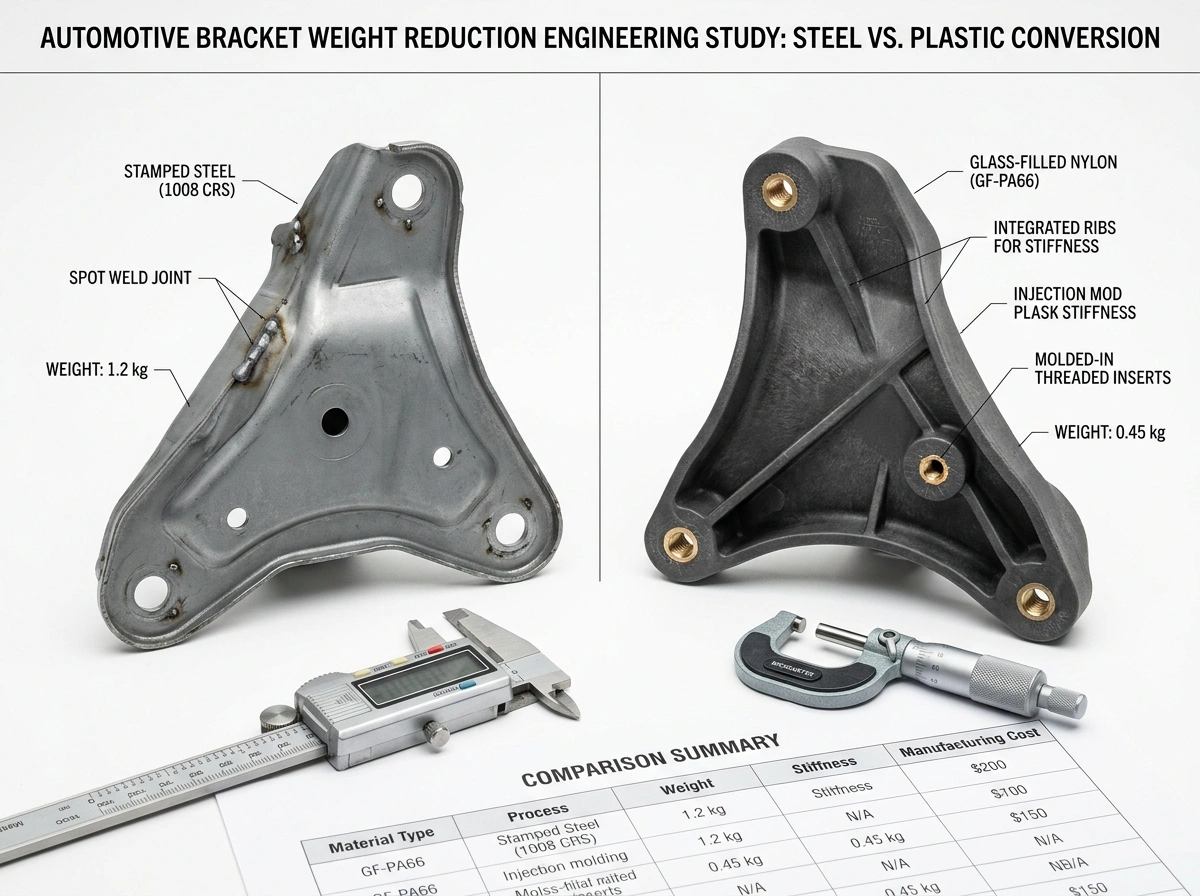
Consider a typical underbody mounting bracket originally stamped from 1.5mm cold-rolled steel, weighing approximately 180 grams, designed to support a moderate static load with occasional vibration cycling.
A converted version in 30% glass-filled PA6, redesigned with strategic ribbing and a revised boss layout to replace the stamped flange stiffness, typically lands in the 70–90 gram range — roughly a 50–60% mass reduction — while meeting the same static and vibration load requirements, once validated through FEA and physical testing. The conversion also consolidated what was a two-piece welded bracket assembly into a single molded part, eliminating a welding operation and a fastener.
This is a representative pattern across many bracket and housing conversions, though exact results depend heavily on the specific load case and geometry constraints of each part.
When Conversion Is NOT the Right Call
Sheet metal to plastic conversion isn't universally beneficial. It's typically a poor fit when:
Extreme structural load exceeds what reinforced plastics can realistically achieve without excessive wall thickness that erodes the weight benefit
Very high temperature exposure (close to engine block or exhaust) exceeds even high-performance plastic resin limits
Low production volume doesn't justify injection mold tooling cost versus a simple stamping die
Tight space constraints don't allow the additional wall thickness plastics typically need to match metal stiffness
A proper feasibility study — comparing load case, volume, temperature exposure, and space envelope — should happen before committing engineering resources to a full conversion program.
Frequently Asked Questions
*How much weight can typically be saved converting sheet metal to plastic?**
Most successful bracket and housing conversions achieve 30–60% mass reduction versus the original steel part, though the exact figure depends heavily on load case and geometry constraints.
*Is glass-filled plastic as strong as steel?**
No — glass-filled engineering plastics don't match steel's absolute strength, but well-engineered geometry (ribbing, wall thickness, boss design) can deliver equivalent functional performance for many automotive load cases at significantly lower weight.
*Does sheet metal to plastic conversion always reduce cost?**
Not always. Material cost per part can be higher for engineering-grade plastics, and tooling investment is significant. The cost case depends on production volume, part consolidation opportunities, and whether downstream processes (welding, e-coating) are eliminated.
*What's the biggest risk in a metal-to-plastic conversion program?**
Treating it as a material substitution rather than a structural redesign. The geometry that worked for stamped metal almost never performs equivalently in plastic without dedicated reinforcement design and FEA validation against the original load cases.
--
*Considering a sheet metal to plastic conversion program?** MG Techworks' design engineers in Pune support automotive OEMs and Tier 1 suppliers with weight reduction feasibility studies, material selection, FEA validation, and tolerance analysis for converted components. Request a free consultation or explore our Sheet Metal Weight Reduction services.