Snap-Fit Design for Automotive Plastic Parts: Avoiding Field Failures
*Quick answer:** Snap-fit design is the engineering of cantilever, torsional, or annular plastic features that allow two parts to assemble without separate fasteners, relying on controlled elastic deflection of the plastic itself. In automotive applications, snap-fits must survive not just initial assembly but years of thermal cycling, vibration, and occasional service disassembly — which means strain calculation, material selection, and fatigue consideration matter far more than in low-stakes consumer product applications.
Snap-fits look simple — a small hook, a little flex, a click. But automotive snap-fits sit in one of the harshest environments a fastening feature can face: temperature swings from -40°C to over 80°C in a closed cabin, constant low-amplitude vibration, and an expectation of zero-rattle performance for the vehicle's entire service life. A snap-fit that passes initial assembly testing can still fail in the field eighteen months later if the strain calculation was wrong from the start. This guide walks through how to design snap-fits that actually hold up.
--
The Three Snap-Fit Types Used in Automotive Plastics
| Type | How It Works | Common Automotive Use |
|---|---|---|
| Cantilever snap-fit | A flexible beam-like arm deflects, then springs back to lock behind a catch feature | Door trim panel clips, glove box latches, IP attachment points |
| Torsional snap-fit | A feature twists along its axis during engagement rather than bending | Rotating latch mechanisms, certain console lid designs |
| Annular (cylindrical) snap-fit | A circular lip flexes radially to snap over a circular boss | Knob attachments, round connector housings, cap-to-body joints |
Cantilever snap-fits are by far the most common in automotive interior applications, so this guide focuses primarily on getting those right.
The Core Engineering Variable: Strain, Not Just Deflection
The single most important calculation in snap-fit design is maximum strain during deflection — not how far the feature moves, but how much the material stretches at its outer fiber during that movement. Exceed the material's allowable strain limit, even briefly during assembly, and you risk micro-cracking that won't show up immediately but will propagate under vibration and thermal cycling until the feature fails — often months after the vehicle has shipped.
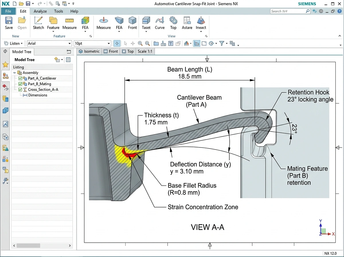
The basic cantilever beam strain equation is:
*ε = (3 × y × t) / (2 × L²)**
Where:
ε = strain at the outer fiber
y = deflection distance
t = beam thickness at the base
L = beam length
This is a simplified rectangular cross-section approximation; real automotive snap-fit geometry (tapered beams, fillets at the base) requires correction factors, which is why FEA validation is standard practice for any production snap-fit design rather than relying on hand calculation alone.
Allowable Strain Limits by Material
| Material | Typical Allowable Strain (Single Assembly) | Typical Allowable Strain (Repeated Cycling) |
|---|---|---|
| PP (Polypropylene) | 4–5% | 2–3% |
| ABS | 2–2.5% | 1–1.5% |
| PA6/PA66 (Nylon, dry) | 5–6% | 2.5–3% |
| PA6/PA66 (Nylon, glass-filled) | 1.5–2% | 0.8–1% |
| POM (Delrin/Acetal) | 4–5% | 2–2.5% |
| PC (Polycarbonate) | 2–2.5% | 1–1.5% |
Two things matter beyond this table. First, glass-filled materials have dramatically lower allowable strain than their unfilled counterparts — a common mistake is reusing an unfilled-material snap-fit geometry after switching to glass-filled resin for stiffness, without recalculating strain limits. Second, repeated-cycling allowable strain (for features intended to be opened and closed in service, like a glove box latch) is always significantly lower than single-assembly strain, because each cycle accumulates fatigue.
Common Snap-Fit Failure Modes in Automotive Applications
Brittle fracture at first assembly — strain exceeded material limit during initial snap, often from beam thickness being too aggressive at the design stage
Delayed fatigue failure — micro-cracks from marginal strain levels propagate after months of vibration, common in glove box and console latch mechanisms
Stress whitening at the base radius — visible cosmetic defect indicating the feature was strained close to its limit, often a warning sign before functional failure
Loss of retention force over time — creep relaxation in the locked position, particularly in materials with poor creep resistance under sustained load
Rattle/squeak (BSR) development — insufficient retention force or interference fit degrading over thermal cycles, leading to micro-movement between parts
Design Checklist for Automotive Snap-Fit Features
Before releasing a snap-fit design for tooling, verify:
Strain calculation completed for the specific material grade (not a generic "similar plastic" assumption), including glass fill content if applicable
Base radius/fillet specified — sharp internal corners at the beam base are the single most common stress concentration leading to premature failure
Draft angle accounted for in the deflection direction, since draft can change the effective beam geometry
Repeated-cycling strain limit used if the feature is intended for service disassembly, not the higher single-assembly limit
Thermal cycling considered — material allowable strain decreases at temperature extremes, and CTE mismatch between mating parts should be checked
FEA validation run against the hand-calculated strain estimate before tooling commitment
Assembly force verified — the insertion force should be within ergonomic assembly limits for the production line, not just within material strain limits
Retention force verified — sufficient to resist the expected service loads (vibration, occupant interaction) without excessive disassembly force
Snap-Fit vs. Mechanical Fasteners: When to Use Each
Snap-fits aren't always the right answer. They generally make sense for:
Cosmetic trim panels with low structural load requirements
Components requiring tool-less service access
High-volume parts where eliminating a fastener and assembly step reduces cost meaningfully
Mechanical fasteners (screws, clips, rivets) remain the better choice for:
High structural load joints, particularly safety-relevant attachments
Joints requiring repeated high-force disassembly/reassembly in service
Applications where snap-fit strain limits can't be met within the available geometry envelope
Frequently Asked Questions
*Can a snap-fit be redesigned after a failure without changing the material?**
Often yes — adjusting beam length, thickness, or base radius can resolve a strain-limit violation without a material change, provided there's geometric room to do so. FEA-based root cause analysis should confirm which variable to adjust before retooling.
*Why do glass-filled materials need more conservative snap-fit design?**
Glass fiber reinforcement increases stiffness and reduces creep, but it significantly lowers the material's allowable strain before microcracking — glass fibers create stress concentration points the base resin doesn't have on its own.
*Is hand calculation enough for production snap-fit design?**
Hand calculation (using the standard cantilever beam strain equation) is a reliable starting point for early design iteration, but production-intent snap-fits — especially in automotive interior applications with safety or repeated-use requirements — should be validated with FEA before tooling commitment.
*How does temperature affect snap-fit performance?**
Most plastics become more brittle (lower allowable strain) at cold temperatures and lose stiffness/strength at high temperatures. Automotive snap-fits must be validated across the full expected temperature range, typically -40°C to 85°C+ for cabin-adjacent components.
--
*Need snap-fit or fastening feature design support for your next automotive program?** MG Techworks' design engineers in Pune provide strain calculation, FEA validation, and DFM review for snap-fit and boss features in automotive interior plastic parts. Request a free consultation or explore our Automotive Interior Plastic Design services.