Reverse Engineering Process: Complete Technical Guide
Introduction: The Strategic Value of Reverse Engineering
In today's competitive manufacturing landscape, reverse engineering has evolved from a simple copying tool to a strategic capability for innovation, competitive analysis, and product improvement. For automotive manufacturers and suppliers, where product development cycles are compressed and competitive intelligence is crucial, reverse engineering provides critical insights into market trends, manufacturing techniques, and design optimization opportunities.
The global reverse engineering market is projected to reach $18.2 billion by 2027, driven primarily by automotive and aerospace applications. For engineering organizations, mastering reverse engineering is no longer optional—it's essential for maintaining competitive advantage, accelerating development cycles, and understanding emerging technologies.
This comprehensive guide will equip you with the knowledge to implement reverse engineering processes effectively, select appropriate technologies, and apply results for maximum business value.
What is Reverse Engineering?
Definition and Scope
*Reverse engineering** is the systematic process of deconstructing an existing product or component to understand its design, architecture, manufacturing methods, and functional principles. Unlike simple copying, modern reverse engineering focuses on understanding the "why" behind design decisions, not just the "what" of physical implementation.
Strategic Applications
*Competitive Intelligence:**
Analyze competitor products for market positioning
Understand manufacturing capabilities and cost structures
Identify technology trends and innovation patterns
Benchmark performance characteristics and features
*Product Improvement:**
Identify design weaknesses and failure modes
Optimize existing designs for better performance
Reduce manufacturing costs through process improvement
Extend product life through design enhancements
*Legacy System Support:**
Document obsolete products without technical documentation
Create digital models for discontinued components
Develop replacement strategies for aging systems
Enable modernization without original manufacturer support
Legal and Ethical Considerations
*Intellectual Property Compliance:**
Patent Analysis: Ensure no patent infringement
Trade Dress Protection: Avoid copying distinctive visual elements
Copyright Compliance: Respect proprietary software and documentation
Contractual Restrictions: Follow customer and industry agreements
*Ethical Guidelines:**
Use reverse engineering for legitimate business purposes
Respect intellectual property rights
Focus on learning and improvement, not direct copying
Maintain professional integrity and industry standards
The Reverse Engineering Process: Step-by-Step Methodology
Phase 1: Project Planning and Scoping
*Objective Definition:**
Clear Goals: Define specific outcomes and success criteria
Scope Boundaries: Establish what will and won't be analyzed
Resource Requirements: Determine equipment, time, and expertise needed
Risk Assessment: Identify potential challenges and mitigation strategies
*Technical Requirements Analysis:**
Accuracy Requirements: Determine measurement precision needed
Material Analysis: Identify materials and their properties
Complexity Assessment: Evaluate geometric complexity and features
Output Format: Define required deliverables and formats
Phase 2: Data Acquisition and Capture
#### 2.1 Non-Contact Measurement Methods
*Traditional Measurement Tools:**
Calipers and Micrometers: Manual measurement of external features
Height Gauges: Surface profiling and contour measurement
Coordinate Measuring Machines (CMM): Point-by-point digitization
Surface Plates: Reference datum establishment
*Applications and Limitations:**
| Method | Accuracy | Speed | Best Applications | Limitations |
|---------|----------|-------|------------------|-------------|
| Calipers | ±0.01mm | Slow | Simple external features | Internal features, complex geometry |
| CMM | ±0.005mm | Medium | Precision features, GD&T verification | Programming time, accessibility |
| Height Gauge | ±0.002mm | Slow | Surface profiles, contours | Limited depth range |
| Surface Plate | ±0.001mm | Very Slow | Reference surfaces | Manual operation, skill-dependent |
#### 2.2 3D Scanning Technologies
*Laser Scanning Systems:**
*Working Principle:**
Laser scanners project a laser line onto the object surface and measure deformation using triangulation. The system captures millions of points to create a detailed 3D representation.
*Technical Specifications:**
Accuracy: ±0.025mm to ±0.05mm typical
Resolution: 0.05mm to 0.1mm point spacing
Speed: 10,000 to 50,000 points per second
Range: Up to 5 meters depending on system
Object Size: 10mm to 2,000mm typical range
*Advantages:**
Fast data capture for large objects
Good accuracy for most automotive applications
Portable systems available for field use
Relatively lower cost than structured light systems
*Limitations:**
Struggles with shiny or reflective surfaces
Cannot capture internal features without disassembly
Accuracy affected by ambient lighting conditions
Limited effectiveness on transparent materials
*Automotive Applications:**
Body Panels: Exterior surface analysis and damage assessment
Interior Components: Dashboard and console surface digitization
Underbody Parts: Frame and suspension component analysis
Wheels and Tires: Rim and tread pattern analysis
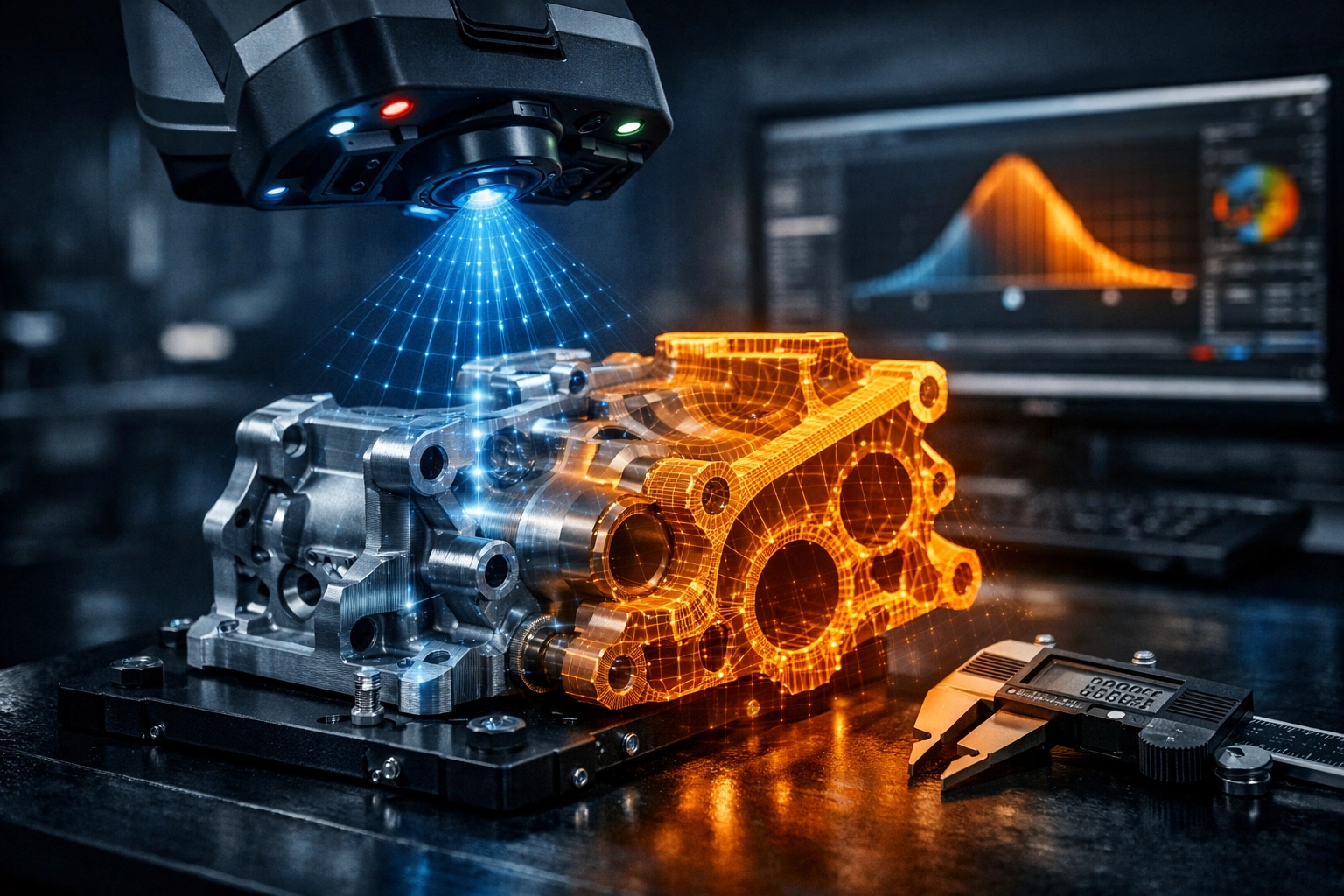
#### 2.3 Structured Light Scanning
*Working Principle:**
Structured light scanners project a series of light patterns onto the object surface and capture deformation with multiple cameras. Triangulation algorithms calculate precise 3D coordinates for each point.
*Technical Specifications:**
Accuracy: ±0.005mm to ±0.015mm typical
Resolution: 0.01mm to 0.05mm point spacing
Speed: 1-5 million points per second
Field of View: 100mm to 500mm diagonal typical
Camera Resolution: 1.3 to 5 megapixels
*Advantages:**
Highest accuracy among non-contact methods
Excellent for complex organic shapes
Captures color and texture information
Less affected by surface finish than laser scanning
*Limitations:**
Higher equipment cost than laser systems
Sensitive to ambient lighting conditions
Requires multiple cameras for complete coverage
Longer setup and calibration time
*Automotive Applications:**
Engine Components: Complex cylinder head and intake manifold shapes
Transmission Housings: Complex geometric forms and mounting features
Suspension Components: Control arms and knuckles with organic curves
Interior Trim: Complex dashboard and door panel geometries
#### 2.4 Computed Tomography (CT) Scanning
*Working Principle:**
CT scanning uses X-ray technology to capture internal and external geometry simultaneously. The system creates cross-sectional images and reconstructs 3D models from volumetric data.
*Technical Specifications:**
Accuracy: ±0.01mm to ±0.05mm depending on material and size
Resolution: 0.01mm voxel size typical for industrial CT
Penetration: Up to 300mm in aluminum, 100mm in steel
Material Density: Can distinguish materials with different densities
*Advantages:**
Captures internal geometry without disassembly
Works with complex assemblies and hidden features
Can identify material defects and inclusions
Non-destructive testing of assembled products
*Limitations:**
Very high equipment cost and maintenance requirements
Limited to smaller parts due to chamber size
Safety requirements for X-ray operation
Longer scan times than optical methods
*Automotive Applications:**
Cylinder Heads: Internal coolant passages and valve seats without disassembly
Transmission Assemblies: Gear arrangements and bearing configurations
Electronic Modules: Internal PCB and component arrangements
Casting Analysis: Internal porosity and defect detection
Phase 3: Data Processing and Point Cloud Management
#### 3.1 Point Cloud Cleanup and Optimization
*Noise Reduction:**
Outlier Removal: Statistical filtering of erroneous points
Smoothing Algorithms: Reduce measurement noise while preserving features
Registration: Align multiple scans into common coordinate system
Decimation: Reduce point density while maintaining accuracy
*Data Quality Assurance:**
Overlap Analysis: Ensure complete coverage from multiple scan angles
Hole Filling: Intelligently fill missing data in occluded areas
Edge Detection: Preserve critical feature boundaries
Uniformity Check: Verify consistent point distribution
#### 3.2 Surface Reconstruction
*Mesh Generation Algorithms:**
Delaunay Triangulation: Creates surface from point cloud
Poisson Surface Reconstruction: Handles complex topology and holes
Advancing Front Algorithm: Progressively builds surface from point cloud
NURBS Surface Fitting: Creates mathematically smooth surfaces
*Quality Metrics:**
Triangle Quality: Aspect ratio and angle analysis
Surface Deviation: Compare mesh to original point cloud
Topology Validation: Ensure water-tight surfaces
Feature Preservation: Verify critical geometric elements
Phase 4: CAD Modeling and Design Intent
#### 4.1 Feature Extraction and Recognition
*Geometric Feature Identification:**
Primitive Shapes: Planes, cylinders, cones, spheres
Freeform Surfaces: Complex curves and organic shapes
Draft Angles: Manufacturing extraction angles
Fillet Radii: Edge and corner treatments
Symmetry Analysis: Identify intentional design symmetry
*Automated Feature Recognition:**
Pattern Recognition: Identify repeated features and arrays
Feature Trees: Hierarchical organization of design elements
Constraint Recognition: Understand mating and assembly relationships
Design Intent Analysis: Infer functional requirements from geometry
#### 4.2 Parametric Modeling
*CAD Software Platforms:**
CATIA (Dassault Systèmes): Aerospace and automotive industry standard
Siemens NX: Comprehensive CAD/CAM/CAE solution
PTC Creo: Parametric modeling with simulation integration
Autodesk Inventor: Mechanical design and documentation
SolidWorks: Popular for small to medium manufacturing
*Modeling Techniques:**
Hybrid Modeling: Combine solid and surface modeling approaches
Direct Modeling: Build geometry without sketches when possible
Master Model Techniques: Create design-intent models for families
Assembly Modeling: Create relationships between components
Parameters and Equations: Drive design changes through mathematical relationships
Phase 5: Validation and Quality Assurance
#### 5.1 Dimensional Verification
*Measurement Methods:**
CMM Inspection: Verify critical dimensions and tolerances
Optical Scanning: Compare physical part to digital model
Surface Analysis: Verify form, profile, and roughness
Functional Testing: Validate fit, form, and function
*Statistical Analysis:**
GD&T Verification: Confirm geometric tolerances and datums
Tolerance Stack-up: Analyze cumulative effects of variations
Capability Studies: Assess manufacturing feasibility
Measurement System Analysis: Evaluate measurement uncertainty
#### 5.2 Documentation and Deliverables
*Technical Documentation:**
2D Drawings: Traditional manufacturing drawings with GD&T
3D Models: Native CAD files for manufacturing and analysis
Step Files: Neutral format for data exchange
Technical Reports: Comprehensive analysis and methodology documentation
*Manufacturing Support:**
Tolerance Analysis: Stack-up studies for assembly feasibility
Manufacturing Drawings: Production-ready documentation
Quality Plans: Inspection and testing procedures
Cost Analysis: Manufacturing cost estimation and optimization
Advanced Reverse Engineering Applications
Case Study 1: Automotive Component Optimization
*Challenge:**
An automotive supplier needed to reverse engineer a competitor's brake caliper for cost reduction and performance improvement. The component featured complex internal geometry, multiple mounting interfaces, and precise hydraulic passages.
*Implementation Process:**
*Phase 1: Strategic Planning**
Competitive Analysis: Identify cost drivers and performance differentiators
Technology Assessment: Analyze manufacturing methods and materials
Risk Evaluation: Patent landscape and IP compliance
Resource Planning: Equipment selection and team allocation
*Phase 2: Data Acquisition**
CT Scanning: Selected for internal hydraulic passage analysis
Laser Scanning: Used for external mounting features
Material Analysis: Identified aluminum alloy composition
Accuracy Requirements: ±0.01mm for critical hydraulic features
*Phase 3: CAD Modeling**
Hybrid Approach: Combined solid and surface modeling
Feature Recognition: Automated identification of mounting patterns
Parametric Design: Created model family for design variations
GD&T Application: Established datum structure and tolerances
*Phase 4: Optimization and Validation**
CFD Analysis: Optimized hydraulic flow patterns
FEA Simulation: Improved structural stiffness and weight
Tolerance Stack-up: Optimized for manufacturability
Prototype Testing: Validated performance improvements
*Results:**
Cost Reduction: 18% manufacturing cost savings
Weight Reduction: 12% component weight reduction
Performance Improvement: 8% braking efficiency increase
Development Time: 40% reduction in design cycle time
Case Study 2: Legacy System Modernization
*Challenge:**
A military vehicle manufacturer needed to reverse engineer obsolete engine control modules for which no technical documentation existed. The components were 20+ years old, with no available spare parts or manufacturer support.
*Implementation Process:**
*Phase 1: System Analysis**
Functional Testing: Reverse engineered operational requirements
Interface Analysis: Documented electrical and mechanical connections
Material Analysis: Identified aging polymers and corrosion patterns
Failure Analysis: Determined wear and failure modes
*Phase 2: Digital Reconstruction**
Circuit Board Scanning: Non-contact measurement of PCB layouts
Component Analysis: Disassembled and analyzed individual components
3D Modeling: Created complete digital assembly
Schematic Generation: Developed electrical documentation
*Phase 3: Modernization Design**
Technology Upgrade: Replaced obsolete electronics with modern components
Material Improvement: Updated to modern, corrosion-resistant materials
Manufacturing Optimization: Design for current production capabilities
Testing Protocol: Comprehensive validation and qualification
*Results:**
System Reliability: 95% reduction in field failures
Maintenance Cost: 70% reduction in lifecycle maintenance costs
Weight Reduction: 25% system weight reduction
Parts Availability: Created digital inventory for on-demand manufacturing
Technology Selection and Equipment Considerations
Accuracy Requirements vs. Application
*High-Accuracy Applications (±0.005mm or better):**
Aerospace Components: Critical flight hardware and engine components
Precision Tooling: Injection molds and stamping dies
Medical Devices: Surgical instruments and implantable components
Optical Components: Lens mounts and precision assemblies
*Medium-Accuracy Applications (±0.01mm to ±0.025mm):**
Automotive Components: Body panels, interior trim, and powertrain
Consumer Products: Electronic housings and appliance components
Industrial Equipment: Pumps, valves, and mechanical assemblies
Replacement Parts: Aftermarket components and service parts
*Standard-Accuracy Applications (±0.05mm to ±0.1mm):**
Large Assemblies: Frame structures and body components
Tooling and Fixtures: Production equipment and jigs
Prototyping: Concept models and fit check parts
Reverse Engineering Studies: Competitive analysis and market research
Cost-Benefit Analysis
*Equipment Investment Analysis:**
| Technology | Initial Cost | Annual Maintenance | Labor Requirements | ROI Period |
|-----------|------------|-------------------|------------------|------------|
| Laser Scanner | $50,000-80,000 | $5,000-8,000 | 0.5 FTE | 2-3 years |
| Structured Light | $80,000-150,000 | $8,000-12,000 | 1.0 FTE | 3-5 years |
| CT Scanner | $300,000-600,000 | $25,000-40,000 | 1.5 FTE | 5-8 years |
| CMM | $100,000-200,000 | $10,000-15,000 | 2.0 FTE | 4-6 years |
*Operational Cost Considerations:**
Software Licenses: Annual subscription and maintenance fees
Training Costs: Initial and ongoing operator training
Facility Requirements: Controlled environment and power requirements
Consumables: Scanning media, calibration artifacts, and replacement parts
Quality Assurance and Process Control
Measurement Uncertainty Analysis
*Sources of Uncertainty:**
Equipment Accuracy: Inherent measurement system limitations
Operator Skill: Experience and technique consistency
Environmental Factors: Temperature, vibration, and lighting
Part Stability: Fixturing and clamping methods
Data Processing: Algorithm and software limitations
*Uncertainty Budget:**
Gage R&R Studies: Repeatability and reproducibility analysis
Statistical Methods: Monte Carlo simulation of measurement variation
Calibration Procedures: Regular verification and adjustment
Documentation: Clear uncertainty reporting and communication
Process Validation Methods
*Physical Verification:**
First Article Inspection: Compare first production to design intent
Dimensional Studies: Statistical analysis of production parts
Fit and Function Testing: Assembly and operational validation
Long-Term Monitoring: Field performance and reliability tracking
*Digital Validation:**
Simulation Analysis: Virtual assembly and tolerance analysis
Manufacturability Assessment: DFM analysis for production feasibility
Cost Estimation: Automated manufacturing cost calculation
Design Review: Cross-functional validation and approval
Future Trends in Reverse Engineering
AI-Enhanced Reverse Engineering
*Machine Learning Applications:**
Automated Feature Recognition: AI algorithms identify design intent
Intelligent Surface Reconstruction: Neural networks create optimal meshes
Predictive Modeling: Anticipate design variations and alternatives
Quality Assessment: Automated defect and anomaly detection
*Benefits:**
Speed Improvement: 50-70% reduction in modeling time
Accuracy Enhancement: Improved feature recognition and reconstruction
Cost Reduction: Less skilled labor required for modeling
Consistency: Standardized processes and repeatable results
Integrated Digital Twin Technology
*Real-Time Reverse Engineering:**
Live Scanning Integration: Continuous data capture and update
Automated Model Updates: Real-time CAD model maintenance
Performance Monitoring: Live comparison of physical vs. digital
Change Detection: Automatic identification of design modifications
*Applications:**
In-Process Quality: Real-time deviation detection during manufacturing
Wear Analysis: Continuous monitoring of tool and component wear
Update Management: Automated configuration control and documentation
Field Support: Remote diagnostics and maintenance planning
Implementation Strategy for Organizations
Phase 1: Capability Development
*Technology Acquisition:**
Equipment Selection: Balance accuracy, speed, and cost requirements
Software Investment: CAD platforms and analysis tools
Facility Preparation: Environmental control and space requirements
Training Programs: Operator skill development and certification
*Process Development:**
Standard Procedures: Documented methodologies and best practices
Quality Systems: Inspection and validation processes
Data Management: File organization and version control
Project Management: Planning and execution frameworks
Phase 2: Pilot Implementation
*Technology Validation:**
Test Projects: Select representative and challenging applications
Method Comparison: Evaluate different technologies and approaches
Process Refinement: Optimize procedures based on lessons learned
Success Criteria: Define measurable outcomes and ROI metrics
*Capability Demonstration:**
Case Studies: Document successful applications and results
Cost-Benefit Analysis: Quantify value and competitive advantage
Risk Assessment: Identify and mitigate potential implementation challenges
Stakeholder Communication: Regular reporting and milestone updates
Phase 3: Full-Scale Operation
*Resource Optimization:**
Workload Balancing: Distribute projects across available capacity
Technology Integration: Incorporate reverse engineering into product development
Continuous Improvement: Ongoing process refinement and optimization
Knowledge Management: Capture and share lessons learned
*Strategic Integration:**
Product Development: Link reverse engineering to design cycles
Competitive Intelligence: Systematic market and technology analysis
Manufacturing Support: Provide manufacturing-ready documentation
Innovation Pipeline: Feed insights into new product development
Conclusion: Strategic Value of Reverse Engineering
Reverse engineering has transformed from a simple copying tool to a strategic capability that drives innovation, competitive advantage, and business growth. Organizations that master reverse engineering gain significant advantages:
*Key Success Factors:**
Technology Integration: Combine multiple scanning and modeling technologies
Process Discipline: Follow systematic methodologies and quality standards
Strategic Application: Focus on business value rather than just copying
Continuous Improvement: Regularly update processes and capabilities
Knowledge Management: Capture and leverage insights across the organization
*Business Impact:**
Accelerated Development: 40-60% reduction in design cycle time
Cost Reduction: 15-30% improvement in manufacturing efficiency
Quality Enhancement: Better understanding of design principles and failure modes
Competitive Intelligence: Deep insights into market trends and technologies
Innovation Enablement: Foundation for new product development and improvement
For automotive manufacturers and suppliers, reverse engineering is not just a technical capability—it's a strategic business tool that enables competitive advantage through better understanding, faster development, and improved products.
How MG Techworks Can Help
At MG Techworks, we provide comprehensive reverse engineering services:
3D Scanning Services using laser, structured light, and CT technologies
CAD Modeling and Reconstruction with design intent analysis
Dimensional Inspection and Validation with statistical process control
Manufacturing Support with DFM analysis and production documentation
Competitive Analysis with technology assessment and benchmarking
Our team of experienced engineers and metrology specialists has helped leading automotive manufacturers accelerate development cycles, reduce costs, and achieve competitive advantage through strategic reverse engineering applications.
*Ready to leverage reverse engineering for competitive advantage?**
Contact MG Techworks to discover how our reverse engineering expertise can transform your product development and manufacturing processes.
Explore our Reverse Engineering services or learn more about our Product Design capabilities for comprehensive product development.*