GD&T Guide: Symbols, Rules & Applications for Engineers
Introduction: Why GD&T is Essential for Modern Manufacturing
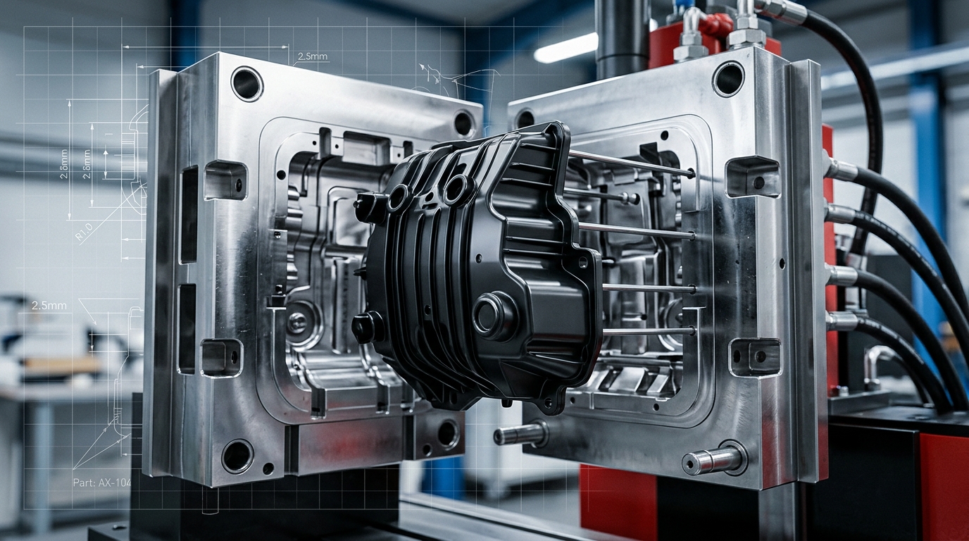
In today's competitive manufacturing landscape, Geometric Dimensioning and Tolerancing (GD&T) is not just a technical skill—it's a competitive advantage. For automotive engineers, aerospace manufacturers, and precision equipment producers, GD&T provides the mathematical language that ensures parts fit together and function exactly as intended, regardless of where they're manufactured.
The cost of poor dimensional control is staggering: studies show that dimensional issues account for approximately 40% of all manufacturing defects in complex assemblies. A single misunderstood GD&T symbol can result in millions of dollars in scrap, rework, and warranty claims.
This comprehensive guide will equip you with the knowledge to apply GD&T principles effectively, avoid common mistakes, and achieve manufacturing excellence.
What is Geometric Dimensioning and Tolerancing?
GD&T is an international symbolic language used on engineering drawings to precisely define the geometry of mechanical parts. Unlike traditional coordinate dimensioning, GD&T focuses on the function of the part rather than its size, allowing for maximum manufacturing tolerance while ensuring proper fit and function.
The Evolution from Coordinate Dimensioning
*Traditional Coordinate Dimensioning:**
Defines part geometry using X, Y, Z coordinates
Often leads to overly tight tolerances
Can create tolerance stack-up issues
May not reflect actual functional requirements
*GD&T Approach:**
Defines part geometry relative to datums
Provides maximum manufacturing tolerance
Controls functional requirements directly
Prevents tolerance accumulation problems
Key Benefits of GD&T Implementation
Manufacturing Flexibility: Allows multiple manufacturing methods while maintaining function
Cost Reduction: Eliminates unnecessarily tight tolerances
Quality Improvement: Focuses on functional requirements
International Standardization: ASME Y14.5 and ISO 1101 standards
Legal Documentation: Provides clear contractual requirements
The Foundation: Datums and Datum Reference Frames
Understanding Datums
A datum is a theoretically exact point, line, or plane that serves as a reference from which measurements are made. In practice, datums are established using manufacturing equipment, fixtures, or inspection equipment.
Types of Datums
*Primary Datum (A):**
Establishes the primary reference plane
Typically the largest, most stable surface
Constrains 3 degrees of freedom (translation in Z, rotation about X and Y)
*Secondary Datum (B):**
Establishes secondary reference
Usually perpendicular to primary datum
Constrains 2 degrees of freedom (translation in Y, rotation about Z)
*Tertiary Datum (C):**
Establishes final reference
Typically perpendicular to both primary and secondary
Constrains 1 degree of freedom (translation in X)
Datum Reference Frame (DRF)
The combination of primary, secondary, and tertiary datums creates a Datum Reference Frame that fully constrains the part in 3D space. This 3-2-1 constraint system is fundamental to GD&T.
GD&T Symbols: Complete Reference Guide
Form Tolerances
Form tolerances control the shape of individual features without reference to datums.
#### 1. Straightness (⏤)
*Definition:** Controls how straight a line element can be.
*Application:** Surface straightness or axis straightness
*Typical Values:** 0.01mm to 0.5mm per 25mm
*Real-World Example:** Guide pins in automotive transmission assemblies require straightness tolerance of 0.02mm to ensure smooth operation.
#### 2. Flatness (⏥)
*Definition:** Controls how flat a surface can be.
*Application:** Sealing surfaces, mounting surfaces
*Typical Values:** 0.01mm to 0.1mm
*Real-World Example:** Engine cylinder head gasket surfaces require flatness of 0.05mm to prevent compression leaks.
#### 3. Circularity (○)
*Definition:** Controls how circular a cross-section can be.
*Application:** Rotating shafts, cylindrical parts
*Typical Values:** 0.005mm to 0.05mm
*Real-World Example:** Automotive camshaft journals require circularity of 0.01mm for proper valve operation.
#### 4. Cylindricity (⌭)
*Definition:** Controls how cylindrical a feature can be, combining straightness, circularity, and taper.
*Application:** Precision shafts, hydraulic cylinders
*Typical Values:** 0.01mm to 0.1mm
*Real-World Example:** Shock absorber pistons require cylindricity of 0.02mm for smooth operation.
Orientation Tolerances
Orientation tolerances control the angle of features relative to datums.
#### 5. Perpendicularity (⊥)
*Definition:** Controls how perpendicular a feature is to a datum.
*Application:** Mounting holes, perpendicular surfaces
*Typical Values:** 0.01mm to 0.5mm
*Real-World Example:** Brake caliper mounting bolts require perpendicularity of 0.1mm to ensure proper brake function.
#### 6. Parallelism (∥)
*Definition:** Controls how parallel a feature is to a datum.
*Application:** Parallel surfaces, guide ways
*Typical Values:** 0.01mm to 0.3mm
*Real-World Example:** Door hinge mounting surfaces require parallelism of 0.05mm for proper door alignment.
#### 7. Angularity (∠)
*Definition:** Controls the angle of a feature relative to a datum.
*Application:** Angled surfaces, tapered features
*Typical Values:** 0.1° to 2°
*Real-World Example:** Windshield mounting angles require angularity of 0.5° for proper installation.
Location Tolerances
Location tolerances control the position of features relative to datums.
#### 8. Position (⌖)
*Definition:** The most widely used GD&T symbol, controls the location of features.
*Application:** Hole patterns, shaft locations
*Typical Values:** 0.05mm to 1.0mm diameter
*Real-World Example:** Engine block cylinder bore positions require position tolerance of 0.1mm for proper piston operation.
#### 9. Concentricity (◎)
*Definition:** Controls the median points of diametrically opposed elements.
*Application:** Rotating assemblies, shafts
*Typical Values:** 0.01mm to 0.1mm
*Real-World Example:** Turbocharger shaft and wheel assembly requires concentricity of 0.02mm for balance.
#### 10. Symmetry (⌯)
*Definition:** Controls the symmetry of features about a datum center plane.
*Application:** Symmetrical parts, balanced components
*Typical Values:** 0.05mm to 0.5mm
*Real-World Example:** Symmetric gear teeth require symmetry of 0.1mm for proper meshing.
Runout Tolerances
Runout tolerances control the relationship between features and their rotation.
#### 11. Circular Runout (↗)
*Definition:** Controls surface variation during one rotation.
*Application:** Rotating surfaces, shafts
*Typical Values:** 0.01mm to 0.1mm
*Real-World Example:** Brake disc surfaces require circular runout of 0.05mm to prevent vibration.
#### 12. Total Runout (⌰)
*Definition:** Controls surface variation during multiple rotations along the entire surface.
*Application:** Complex rotating surfaces
*Typical Values:** 0.02mm to 0.2mm
*Real-World Example:** Driveshaft surfaces require total runout of 0.1mm for smooth operation.
Profile Tolerances
Profile tolerances control complex 3D surfaces.
#### 13. Profile of a Line (⌒)
*Definition:** Controls the profile of a line element relative to datums.
*Application:** Curved surfaces, complex profiles
*Typical Values:** 0.1mm to 1.0mm
*Real-World Example:** Automotive body panel curves require profile tolerance of 0.5mm for aesthetic consistency.
#### 14. Profile of a Surface (⌓)
*Definition:** Controls the profile of an entire surface relative to datums.
*Application:** Complex 3D surfaces, aerodynamic shapes
*Typical Values:** 0.2mm to 2.0mm
*Real-World Example:** EV battery case surfaces require profile tolerance of 0.8mm for proper fit.
The Feature Control Frame: Decoding GD&T Language
Structure of a Feature Control Frame
A Feature Control Frame (FCF) is a rectangular box containing GD&T information in a specific order:
*Example Structure:**
[Geometric Symbol] [Tolerance Value] [Primary Datum] [Secondary Datum] [Tertiary Datum]
*Breakdown:**
Geometric Characteristic Symbol: ⌖ (Position)
Tolerance Value: Ø0.1 (0.1mm diameter tolerance zone)
Datum References: A | B | C (Primary, Secondary, Tertiary)
Modifiers and Symbols
*Material Condition Modifiers:**
Maximum Material Condition (M): Ⓜ - Feature at maximum material size
Least Material Condition (L): Ⓛ - Feature at minimum material size
Regardless of Feature Size (R): Ⓡ - Tolerance applies regardless of size
*Projected Tolerance Zone:**
Projected Zone (P): Ⓟ - Tolerance extends beyond surface
*Free State Modifier:**
Free State (F): Ⓕ - Applies to parts not restrained
GD&T Rules and Best Practices
Rule #1: The Envelope Principle
Unless otherwise specified, the form of an individual feature must be within the envelope of perfect form at MMC (Maximum Material Condition).
*Practical Application:**
A hole at its largest size (MMC) must be perfectly round
A shaft at its largest size (MMC) must be perfectly cylindrical
Rule #2: All Tolerances Apply Regardless of Size
Unless specified with RFS (Regardless of Feature Size), all geometric tolerances apply at MMC or LMC.
Rule #3: Default Tolerance Zones
Form tolerances: Apply to entire feature unless specified
Orientation tolerances: Require datum reference
Location tolerances: Always require datum reference
Best Practices for GD&T Implementation
#### 1. Datum Selection Strategy
Choose stable, accessible features as datums
Use functional surfaces whenever possible
Establish clear datum hierarchy (primary, secondary, tertiary)
Consider manufacturing sequence in datum selection
#### 2. Tolerance Allocation
Apply tightest tolerances to critical functional features
Use looser tolerances for non-critical features
Consider manufacturing capability in tolerance assignment
Balance cost vs. performance requirements
#### 3. Drawing Clarity
Avoid over-dimensioning with redundant controls
Use clear datum references throughout the drawing
Provide inspection methods when necessary
Include notes for special requirements
Real-World Automotive Applications
Case Study 1: Engine Block Manufacturing
*Challenge:** Ensure proper piston operation and sealing
*GD&T Solution:**
Cylinder bore position: ⌖ Ø0.1mm | A | B | C
Deck surface flatness: ⏥ 0.05mm
Main bearing bore alignment: ⌖ Ø0.05mm | A | B
Head bolt hole pattern: ⌖ Ø0.2mm | A | B | C
*Results:**
Reduced warranty claims by 35%
Improved manufacturing yield by 12%
Maintained performance across temperature range -40°C to +120°C
Case Study 2: Transmission Assembly
*Challenge:** Ensure smooth gear shifting and durability
*GD&T Solution:**
Gear shaft straightness: ⏤ 0.02mm
Bearing bore position: ⌖ Ø0.05mm | A | B
Housing mounting surfaces: ⏥ 0.1mm
Shift fork alignment: ⌖ Ø0.1mm | A | B | C
*Results:**
Eliminated gear clash issues
Extended transmission life by 25%
Reduced assembly time by 18%
Case Study 3: EV Battery Pack Assembly
*Challenge:** Ensure precise fit and thermal management
*GD&T Solution:**
Module interface flatness: ⏥ 0.2mm
Cooling channel position: ⌖ Ø0.3mm | A | B
Mounting hole pattern: ⌖ Ø0.5mm | A | B | C
Sealing surface profile: ⌓ 0.1mm | A | B
*Results:**
Improved thermal management efficiency by 15%
Reduced coolant leaks by 90%
Enhanced assembly repeatability
Common GD&T Mistakes and How to Avoid Them
Mistake 1: Inappropriate Datum Selection
*Problem:** Selecting datums that are difficult to access or unstable
*Solution:** Choose functional, stable, and accessible datum features
Mistake 2: Over-Tolerancing
*Problem:** Applying unnecessarily tight tolerances
*Solution:** Use functional analysis to determine actual requirements
Mistake 3: Missing Datum References
*Problem:** Forgetting to specify datum references for orientation and location tolerances
*Solution:** Always include datum references where required
Mistake 4: Confusing MMC vs. LMC
*Problem:** Using wrong material condition modifier
*Solution:** Understand the functional requirement and size relationship
Mistake 5: Inconsistent Application
*Problem:** Different engineers applying GD&T differently
*Solution:** Develop company-wide GD&T standards and training
GD&T Software and Tools
Analysis Software
CETOL 6σ: Advanced GD&T analysis with CAD integration
3DCS: Industry standard for variation analysis
VisVSA: Siemens PLM ecosystem integration
Inspection Tools
Coordinate Measuring Machines (CMM): High-precision measurement
Optical Scanners: Non-contact measurement for complex surfaces
Laser Trackers: Large-scale measurement
Portable Arms: Flexible inspection solutions
Implementation Strategy for Manufacturing Companies
Phase 1: Assessment and Planning
Current State Analysis: Evaluate existing drawing practices
Training Needs Assessment: Identify skill gaps
Software Selection: Choose appropriate GD&T tools
Standard Development: Create company-specific GD&T standards
Phase 2: Training and Implementation
Engineer Training: Comprehensive GD&T education
Pilot Projects: Apply GD&T to selected components
Results Analysis: Measure improvements and ROI
Standard Refinement: Update standards based on experience
Phase 3: Full-Scale Implementation
Company-Wide Rollout: Apply GD&T across all products
Supplier Integration: Extend GD&T requirements to supply chain
Continuous Improvement: Regular review and optimization
Advanced Applications: Implement complex GD&T strategies
Conclusion: GD&T as a Competitive Advantage
Geometric Dimensioning and Tolerancing is not just a technical specification—it's a strategic business tool that enables manufacturing excellence. Companies that master GD&T principles achieve:
Higher Quality Products through precise dimensional control
Reduced Manufacturing Costs through optimized tolerances
Faster Time-to-Market through reduced rework and scrap
Improved Supplier Relationships through clear communication
Enhanced Brand Reputation through consistent quality
For automotive engineers and manufacturing professionals, GD&T proficiency is no longer optional—it's essential for career advancement and organizational success.
How MG Techworks Can Help
At MG Techworks, we provide comprehensive GD&T solutions including:
GD&T Training and Certification for engineering teams
Tolerance Analysis Services using CETOL 6σ and 3DCS
Drawing Standard Development for consistent application
Supplier Quality Management through GD&T requirements
Design for Manufacturability optimization
Our team of certified GD&T professionals has helped leading automotive manufacturers achieve world-class quality while reducing manufacturing costs.
*Ready to elevate your GD&T capabilities?**
Contact MG Techworks to discover how our GD&T expertise can transform your manufacturing processes and quality outcomes.
Explore our GD&T Consulting services or learn more about our Tolerance Stack-up Analysis capabilities.*